To open the device, you have to remove the rubber bumpers on the sides (which can be replaced with rack-ears). Two of the tiny screws on each side don't have to be removed, this lets the bottom shell of the case keep more mechanical strength. Then two halves slide open, an L-shaped top-plus-front-side part, and the rest enclosing sides, bottom and back side.
In the inside, you can find the
power supply, a
digital board (+ analog outputs) and a stack of
three boards mainly responsible for the analog mic/line inputs. The topmost board (which I didn't remove because it's attached to the case by all the XLR connectors) mainly has connectors and the headphone amp. The middle board carries circuitry for the actual mic preamp. The bottom board has a few opamps and the ADCs for the analog inputs.
Power Supply
Generally the manufacturing is pretty nice and everything looks produced to tight tolerances. I could see no gaps, nothing loose. The only downside I see is the powersupply and the mains connector: The supply gets very hot during normal operation (and no devices running on phantom power were connected during the few hours it was in operation before opening the case). The mains connector is isolated with an additional layer of sticky tape, and fastened with hot glue. This looks rather sloppy.
Interestingly Behringer (the Music Group) designed their own supply!
Digital/DSP (+analog output) PCB
People are generally annoyed by the lack of support for WPA/WPA2 with the builtin WiFi access point. It's essentially a
Microchip MRF24WG0MB Module
The USB audio interface seems to be powered by a
XMOS 16L7C10 1000 MIPS, 128 kB SRAM, 32-bit multicore microcontroller and its associated
Microchip USB3340 Enhanced Single Supply Hi-Speed USB ULPI Transceiver.
The actual user-facing functionality obviously is orchestrated by a
Freescale MCIMX253DJM4A i.MX25 400 MHz, single core, ARM 926EJ-S, the network is connected with a standard
Microchip LAN8720A Small Footprint RMII 10/100 Ethernet Transceiver.
The eight XLR analog outputs are fed by a
CS4385 Cirrus Logic octal 24 bit DAC, the
CS4272 Cirrus Logic 24 bit stereo audio codec feeds the headphone output and digitizes the line input (ch 17/18). [it's the only ADC/DAC left after accounting for the 8 analog outputs and 16 analog inputs and corresponding octal converters].
Routing of signals probably is taken care of by the logic inside this
Xilinx XC6SLX4 (Spartan 6) FPGA. It's the smallest of the Spartan 6 family -- and while it has 216 kBit of blockram and 8 "DSP Slices" which feature multipliers, adders and accumulators, I doubt that it does any computational work. Maybe it scales the output level or so, though...
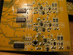
Mic/Line ADC
The most interesting chip on the ADC board (bottom-most in the three-board stack) is the Cirrus Logic
CS5368 octal 24bit ADC. There are two of them, for 16 inputs in total. There are also a bunch of NJM4580 (1+1/2 for each channel), likely for a final level adjust and to drive the differential inputs of the ADCs.
Mic Preamp
The board with the mic preamps is rather interesting. The layout seems to be a conventional frontend using discrete transistors as first stage amplification and a NJM4580 as a differential amplifier. There are two
Coolaudio V411 analog switches per channel to adjust the gain, and quite a few shift registers to provide the control inputs to the analog switches.
Connector PCB
The connector PCB is very uninteresting. One very thoughtful detail, though, is that they drilled holes beneath the XLR/TRS combo jacks. If you ever had to desolder one of those because the TIP of a TRS connector broke off you appreciate this. I did not remove this board, because it's held in place by dozens of screws on the XLR jacks.
A OPAMP labeled JRC8074A seems to be the headphone amplifier.


14 comments:
Thanks for the work... Fascinating look at a device I use every gig.
Fine! Love the photos and explanations. After I've read this post it looks like I'm buying this stuff.
Currently I'm using Mackie Onyx and time has come for an upgrade.
Hi guys i have a Behringer XR12. Today when i had it on its just popped and i could tell from the smell that something blew. I have been told that i probably need to change the power supply. Any idea where i can get a replacement power supply?
Have you emailed Behringer support? You could also have a look at the supply, maybe is repairable.
Hi Chris,
Really appreciate the advanced insight. I have an XR18. Pre amp gains are intermittent and will default to a set gain with limited range. -12 to +60 will minimally move the input swing.
Reflashed firmware, reworked connectors etc. Sometimes behaves then gain alteration on one channel will crash others and you will get limited gain control and end up high or low on channels. Channel 5 seems to always be a dud now-gain low and moves minimally when channel gain is full +60 or -12. any notions would be appreciated- I will eventually go to Behringer with it and would like to have something intelligent to say if possible.
Thanks
Duke
Hey Duke, the gain is set by the "Coolaudio V411" analog switches and the resistors around them on the mic preamp board. The analog switches in turn are controlled by the outputs of the shift registers. Check if the signals on the shift-registers look fine (clock, data in, latch-output) on the mic-preamp board.
As you've written that gain alterations on one channel corrupt the gain on others, it has to be the case that clock/data through the shift-registers goes out of sync. So I expect a dodgy connection there.
Hey Chris, Thanks for the teardown. I'm having an issue on a single channel where, once we enable phantom power, consistent noise can be heard, but only when a condenser mic or active DI is connected to the input. Additionally, when using a passive DI, almost no signal can be heard. The strange part is, when using the 1/4" input of the same channel, it seems ok, but i only have a line level going in to test. I'm thinking I have a problem with the preamp before the A/D conversion. I'm curious as to what your thoughts are and where I should start looking. If I could pin-point the issue, I'd order the components and replace them.
Hi Tyler, I would guess that this is a problem with one of the two symmetrical signals of the microphone-level (XLR) input. I would guess that most likely the socket or its soldering is mechanically broken, test the continuity of both legs (hot & cold) from the socket to one of the pins on the 0,1" pin header connecting the uppermost (connector) PCB to the middle (preamp) PCB.
You should be able to compare continuity for the broken channel to a working one.
Good luck repairing your mixer!
I ended up taking the entire input card off the faceplace of the mixer. I believe I have some failed resistors next to the XLR port. I'm not getting any continuity from the port to the board connector. Next steps, determine which ones and there proper values from a neighbor input and determine if the capacitors nearby are ok. Would be nice to have a schematic.
Hi Chris,
We have an XR18 mixer and experience intermittent volume drops with the left main output. We tried swapping cables with the right main out, but that didn't change anything.
The volume will suddenly drop (more than 6dB) and will return to normal by itself after a few minutes. Again, this is the left main output only.
I have not had a look inside yet, but I think maybe one of the flat cable connectors has come loose. Any ideas?
Thanks,
Robert
Hi +erpece,
-6dB is typical if you loose one of the two conductors (Hot/Cold) in an XLR. Your signal amplitude drops to one half, and this is pretty precisely 6dB).
If the flat cable connectors would come loose, your signal should either vanish completely, or be pretty garbeled as the flex connectors only carry digital information.
Chris
Thanks Chris. I had a look inside and all connectors looked fine.
What do you mean by the conductors - the XLR cable or the mixer? The signal does not drop exactly 6dB, but a significant amount. The sound is sometimes a bit distorted as well, like a loose connection that is being wiggled. Will have to rule out things - do you have suggestions?
Anywhere between the opamps/drivers inside the mixer up to your crossover/amplifier/active speakers.
If I may suggest, look for broken traces on the bottom most PCB on which the connectors are soldered. That's where I'd look first.
Thanks again!
Post a Comment