Here's a Yamaha DGX-620 keyboard with a broken LCD. Judging from the fact that there are quite a few videos and tutorials on how to exchange a broken LCD with the proper spare part, I'd reckon these LCDs break quite easily and often.

(Broken LCD)

(Original LCD module: The slightly kink in the flexfoil is enough to ruin the module, this slight damage is, unfortunately, not repairable.)
I was a little surprised to get a quote of 130€ ($150) for the replacement (Yamaha Part # WG299100), and I was looking for a replacement that's cheaper. As this is a fill-in instrument, and long out of warranty, I wouldn't mind not getting the original part. Also I don't mind the tinkering.
Enter Pollin, a company selling electronic remnants, such as bags with 1kg of capacitors, sold as “perfect for tinkering”. By chance, they sell a “LCD-Modul NAN YA LTC79H202T50K, 240x320” (order #121307, €4/$5) which, on closer examination, is electrically 100% compatible to the Yamaha display. Only with a slightly different, smaller shape, and with a different pinout. Also, they sell the exact same flex-cable that Yamaha uses to connect the LCD to the CPU board: Flexprint-Kabel AXON FFC1.00A14/0200L5-5-10-10 (#562251) (€1).

(Pollin: Product Page)


(cheap replacement LCD)
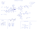
Looking into the datasheet of the LCD provided by Pollin and the Yamaha DGX-620 service manual easily found online, it's clear that electrically the display is compatible.

(Yamaha)

(Pollin LCD Module)
FR (first row) is FLM (first line marker), LP (line pulse?) is CL1 (data latch), XCK (x? clock) is CL2 (shift clock). Everything else has identical designators. Sanding off the back of the replacement LCDs PCB a little to have good bonding to epoxy glue...

(replacement LCD, before gluing down flex cable)
(sanding off the back of the PCB and the white flex-cable, so that the epoxy sticks better, you can see the residue from a first attempt: The blue plastic on the flex cable didn't stick)

(jumper wires)
Ugly patching of wires from the 14-in cable to the pads on the LCD according to pinouts shown above. After soldering the wires (which is hard on the flexfoil, as the plastic melts and the copper traces of the flexfoil will move around, creating shorts) and emitting a few prayers to the deity of choice, a picture appears! :-)

(first signal on replacement LCD screen)
Then I added the display to the original plastic part from which I removed both the LCD logic and all the light spreading works. The complete LCD module almost fits in the cutout for the old glass, only a small plastic ridge had to be removed with a xacto-knive. I had to add a small slot for the flexcable, to feed through and added a hole for the big blob of goo by which I glued down the cables so that they don't become loose.

(cutout for big lump of wires and goo)
The end result: A replaced LCD screen for €4. But I had to invest a few hours of work, which in this case I didn't mind.

(replaced screen on the Yamaha keyboard)
Update: As Ulrich pointed out, one can directly solder the cables for the LCD backlight to the cables going to the two-bin connector on the power supply on more recent models of the keyboard. Some onlder ones have high-voltage for an electroluminiscent foil, though, so beware.
Here are Ulrich's Photos: