Thursday, January 17, 2019
local DNS resolver, forwarding LAN/DHCP domain to your plasic router
This summary is not available. Please
click here to view the post.
Saturday, January 05, 2019
i2c on your unused/legacy VGA output
Almost every PC/notebook still has a VGA connector, which can be used as a very cheap way to quickly test various i2c peripherals. On a VGA connector, it would have been used to query the remote monitor for its supported resolutions, but most graphics drivers in Linux just use the
kernel's generic i2c support.
This is a quick note for myself, so that I can easily copy & paste whenever needed again ;-).
From the linked Wikipedia page:
Pin 9 KEY/PWR formerly key, now +5V DC, powers EDID EEPROM chip on some monitors
Pin 10 GND Ground (VSync, DDC)
Pin 12 ID1/SDA formerly Monitor ID bit 1, I²C data since DDC2
Pin 15 ID3/SCL formerly Monitor ID bit 3, I²C clock since DDC2
Step 1, make sure your graphics card actually exports this i2c device (check the names of all busses in /sys/bus/i2c/devices).
$ grep "" /sys/bus/i2c/devices/i2c-*/name
/sys/bus/i2c/devices/i2c-0/name:SMBus I801 adapter at 0580
/sys/bus/i2c/devices/i2c-1/name:i915 gmbus ssc
/sys/bus/i2c/devices/i2c-2/name:i915 gmbus vga
/sys/bus/i2c/devices/i2c-3/name:i915 gmbus panel
/sys/bus/i2c/devices/i2c-4/name:i915 gmbus dpc
/sys/bus/i2c/devices/i2c-5/name:i915 gmbus dpb
/sys/bus/i2c/devices/i2c-6/name:i915 gmbus dpd
/sys/bus/i2c/devices/i2c-7/name:DPDDC-B
/sys/bus/i2c/devices/i2c-8/name:DPDDC-C

Step 2, make sure a user can conveniently access this bus without becoming root.
$ cat /etc/udev/rules.d/99-i2c-vga-chmod.rules
ACTION=="add", SUBSYSTEM=="i2c-dev", ATTR{name}=="i915 gmbus vga", MODE="0660", GROUP="users", SYMLINK+="i2c-vga"
#
# udevadm info -a -p \$(udevadm info -q path -n /dev/i2c-2)
#
# Udevadm info starts with the device specified by the devpath and then
# walks up the chain of parent devices. It prints for every device
# found, all possible attributes in the udev rules key format.
# A rule to match, can be composed by the attributes of the device
# and the attributes from one single parent device.
#
# looking at device '/devices/pci0000:00/0000:00:02.0/i2c-2/i2c-dev/i2c-2':
# KERNEL=="i2c-2"
# SUBSYSTEM=="i2c-dev"
# DRIVER==""
# ATTR{name}=="i915 gmbus vga"
#
# looking at parent device '/devices/pci0000:00/0000:00:02.0/i2c-2':
# KERNELS=="i2c-2"
# SUBSYSTEMS=="i2c"
# DRIVERS==""
# ATTRS{name}=="i915 gmbus vga"
(...)
Step 3, make sure the i2c-dev kernel module is loaded upon boot.
$ cat /etc/modules-load.d/i2c-dev.conf
i2c-dev

Step5, Profit!
(I'm using a HYT271 humidity and gemperature sensor for testing, it's showing 39 %rh and 26 °C, the small utility is by David Wragg and to be found on github.)

A quick warning, these i2c-busses are often bit-banged and will consume a considerable amount of cycles on your 3Ghz Octacore i7 while clocking out a few kBits/second via i2c. :-)
kernel's generic i2c support.
This is a quick note for myself, so that I can easily copy & paste whenever needed again ;-).
From the linked Wikipedia page:
Pin 9 KEY/PWR formerly key, now +5V DC, powers EDID EEPROM chip on some monitors
Pin 10 GND Ground (VSync, DDC)
Pin 12 ID1/SDA formerly Monitor ID bit 1, I²C data since DDC2
Pin 15 ID3/SCL formerly Monitor ID bit 3, I²C clock since DDC2
Step 1, make sure your graphics card actually exports this i2c device (check the names of all busses in /sys/bus/i2c/devices).
$ grep "" /sys/bus/i2c/devices/i2c-*/name
/sys/bus/i2c/devices/i2c-0/name:SMBus I801 adapter at 0580
/sys/bus/i2c/devices/i2c-1/name:i915 gmbus ssc
/sys/bus/i2c/devices/i2c-2/name:i915 gmbus vga
/sys/bus/i2c/devices/i2c-3/name:i915 gmbus panel
/sys/bus/i2c/devices/i2c-4/name:i915 gmbus dpc
/sys/bus/i2c/devices/i2c-5/name:i915 gmbus dpb
/sys/bus/i2c/devices/i2c-6/name:i915 gmbus dpd
/sys/bus/i2c/devices/i2c-7/name:DPDDC-B
/sys/bus/i2c/devices/i2c-8/name:DPDDC-C

Step 2, make sure a user can conveniently access this bus without becoming root.
$ cat /etc/udev/rules.d/99-i2c-vga-chmod.rules
ACTION=="add", SUBSYSTEM=="i2c-dev", ATTR{name}=="i915 gmbus vga", MODE="0660", GROUP="users", SYMLINK+="i2c-vga"
#
# udevadm info -a -p \$(udevadm info -q path -n /dev/i2c-2)
#
# Udevadm info starts with the device specified by the devpath and then
# walks up the chain of parent devices. It prints for every device
# found, all possible attributes in the udev rules key format.
# A rule to match, can be composed by the attributes of the device
# and the attributes from one single parent device.
#
# looking at device '/devices/pci0000:00/0000:00:02.0/i2c-2/i2c-dev/i2c-2':
# KERNEL=="i2c-2"
# SUBSYSTEM=="i2c-dev"
# DRIVER==""
# ATTR{name}=="i915 gmbus vga"
#
# looking at parent device '/devices/pci0000:00/0000:00:02.0/i2c-2':
# KERNELS=="i2c-2"
# SUBSYSTEMS=="i2c"
# DRIVERS==""
# ATTRS{name}=="i915 gmbus vga"
(...)
Step 3, make sure the i2c-dev kernel module is loaded upon boot.
$ cat /etc/modules-load.d/i2c-dev.conf
i2c-dev
Step 4, solder a matching cable from 15pin DSUB to whatever is convenient for you, I suggest some individual connectors for pin headers.

(I'm using a HYT271 humidity and gemperature sensor for testing, it's showing 39 %rh and 26 °C, the small utility is by David Wragg and to be found on github.)

It should be noted that this will obviously work almost identical on DVI/DisplayPort/HDMI outputs, your motherboard's SMBUS, your random USB peripheral that exposes an i2c bus, ...
A quick warning, these i2c-busses are often bit-banged and will consume a considerable amount of cycles on your 3Ghz Octacore i7 while clocking out a few kBits/second via i2c. :-)
Saturday, May 12, 2018
Behringer X32 and S16 Preamp Noise
I got myself a Behringer X32 Compact mixing desk and Behringer S16 Stageboxes. Because sometimes I record classical concerts, or have ambient microphones that get very little signal, I wanted to verify the preamp performance to avoid nasty surprises.
To establish the voltage scale when recording, a sine-generator generating 1kHz was fed into a passive DI box, and adjusted in amplitude, so that a 1Vrms signal was present on the DI box XLR output. This 1Vrms signal could be easily measured with a TRMS multimeter. Then both the 20dB pad on the DI-box and a 40dB pad on the function generator were engaged, so that a 1mVrms signal is output on the DI box. This sinewave was fed into all devices under test at maximum gain. (See Fig. 2)
Sucessively the XLR connection to the DI box was removed and the input was shorted. A 2nd recording was then made, with identical gain settings only capturing the noise. (See Fig. 1)
Preamps tested were:
- EchoAudio EchoFire 4, which uses a now obsolete SSM2017 from which noise performance is known and documented
- Preamps within the X32 Compact mixing console, using the local XLR input
- Preamps within the two S16 stage boxes
In python (using numpy), the rms of the sinewave-recording was calculated relative to digital full-scale and the noise recording scaled with the resulting factor (e.g. -21.0 dBrms/full-scale for the EchoFire4 recording). From this data the noise density in nV/√Hz was calculated using Scipy's scipy.signal.welch results.
The spikes present are most likely caused by switching voltage regulators within, or in vincinity of, the devices. Generally the Behringer preamps have slightly higher noise than the very respectable SSM2017 within the EchoAudio firewire interface, but all in all the difference is pretty much irrelevant (approx. ~1.5dB more noise than the SSM2017, adds approx. 3 dB to the thermal noise of the 200Ω resistor) for practical use.

Fig1: Noise Analysis (with inputs shunted by 200Ω)

Fig2: Reference Recording of 1mVrms, 1kHz Sine Wave
Useful Links
Monday, September 11, 2017
VHDL Testbench using Oscilloscope Waveforms
I got a little tired of writing a generator for synthetic data in a VHDL testbench, so I thought, maybe just use an oscilloscope trace with real-workd data for this purpose.
So, here's the VHDL code, I've only captured one channel and it's stored as unsigned 8-bit characters, so everything is very easy.

So, here's the VHDL code, I've only captured one channel and it's stored as unsigned 8-bit characters, so everything is very easy.
signal aes3_in : std_logic;
signal aes3_analog : natural;
type t_stim_file is file of character;
data_in: process
-- waveform captured on a rigol oscilloscope, 1ch, 8bit, 1GS/s
file stim_file : t_stim_file open read_mode is "aes_48khz_24bit.wfm";
variable v : character;
variable n : natural range 0 to 255;
begin
-- skip over the first 3300 bytes, header of the wfm file
for i in 0 to 3300 loop
read(stim_file, v);
end loop;
while not endfile(stim_file) loop
read(stim_file, v);
n := character'pos(v);
aes3_analog <= n;
aes3_in <= '1' when n > 90 else '0';
wait for 1 ns; -- 1GHz sampling rate
end loop;
assert false report "end of test" severity failure; -- end testbench here
end process;

Monday, July 24, 2017
Mixing Station X Air Pro XR18 Default Layout
Working with a Behringer XR18 Mixer and using the brilliant Mixing Station Air software, I've made a custom layout for it. It can be downloaded from github.

Thursday, March 23, 2017
Roland TD-25 (Drum Sound Module) Pinout and Waveforms
Debugging an issue with a Roland TD-25K electronic drum set.
First, here are the outputs of the trigger-pads. Yellow is "tip" of a TRS connector, cyan is "ring". Both the bell and the dampening signals of the cymbals connect to the ring and there's a constant voltage offset (which you don't see because the 2nd (cyan) channel was AC coupled.
PDX-100 Snare Pad


CY-13R Ride Cymbal, "Cymbal" connector:


Ride Cymbal, "Bell" connector:

Also, I traced the pinout of the Roland TD-25 multipin/dsub connector.

/--+
+-/ |
| O | 1 KIK-T
T1-T 14 | O |
| O | 2 KIK gnd
T1-R 15 | O |
| O | 3 SNR-T
T1 gnd 16 | O |
| O | 4 SNR-R
T2-T 17 | O |
| O | 5 SNR gnd
T2-R 18 | O |
| O | 6 HH+T2 gnd
T3 gnd 19 | O |
| O | 7 HH-T
T3-T 20 | O |
| O | 8 HH-R
T3-R 21 | O |
| O | 9 HHC gnd
RD/RDB gnd 22 | O |
| O | 10 HHC-T
RD-R 23 | O |
| O | 11 CR1 gnd
RD-T 24 | O |
| O | 12 CR1 T
RDB-R 25 | O |
| O | 13 CR1 R
+-\ |
\-+
gnd: sleeve/ground, T: tip, R: ring
T1/T2/T3: Tom 1, 2, 3
RD: Ride
RDB: Ride Bell
HH: Hihat
HHC: Hihat pedal
KIK: Kick/Bassdrum
SNR: Snare
CR1: Crash Cymbal
Wednesday, November 09, 2016
Archlinux on the Toradex T20 (with Archlinux' kernel)
This is a followup on my earlier blogpost Archlinux on the Toradex T20 from 2012.
I happened to resurrect my old Toradex NVidia Tegra T20 / Colibri / Iris eval-board, which I had running using Toradex' kernel back in 2012 already. And it's amazingly smooth to run the stock Archlinux-Arm distribution for ARM7 CPUs on it, as I found out:
You'll need:
env default -f
Update: I just realized, the variable "fdtaddr" I used initially is used by u-boot internally and overwritten on every boot, don't use it then :-).
Bootup:
U-Boot 2011.06-dirty (Dec 18 2014 - 22:27:35)
TEGRA2
DRAM: 512 MiB
NAND: 1024 MiB
MMC: Tegra2 SD/MMC: 0
Board: Toradex Colibri T20
Net: Net Initialization Skipped
No ethernet found.
Hit any key to stop autoboot: 0
Partition Map for MMC device 0 -- Partition Type: EFI
Part Start LBA End LBA
gpt1 0x800 0x407FF
gpt2 0x40800 0x1D47BDE
reading uimage
5623992 bytes read
reading dtbs/tegra20-iris-512.dtb
28979 bytes read
## Booting kernel from Legacy Image at 00408000 ...
Image Name: Linux Kernel
Created: 2016-11-08 21:31:41 UTC
Image Type: ARM Linux Kernel Image (uncompressed)
Data Size: 5623928 Bytes = 5.4 MiB
Load Address: 00008000
Entry Point: 00008000
Verifying Checksum ... OK
## Flattened Device Tree blob at 01000000
Booting using the fdt blob at 0x1000000
Loading Kernel Image ... OK
OK
Loading Device Tree to 01ff5000, end 01fff132 ... OK
Starting kernel ...
[ 0.000000] Booting Linux on physical CPU 0x0
[ 0.000000] Linux version 4.8.6-1-ARCH (builduser@leming) (gcc version 6.2.1 20160830 (GCC) ) #1 SMP Mon Oct 31 23:22:19 MDT 2016
I happened to resurrect my old Toradex NVidia Tegra T20 / Colibri / Iris eval-board, which I had running using Toradex' kernel back in 2012 already. And it's amazingly smooth to run the stock Archlinux-Arm distribution for ARM7 CPUs on it, as I found out:
You'll need:
- a SD-card formatted using the EFI partition table format (the stock uboot for whatever reason didn't like it when I had it partitioned as MBR)
- two partitions, one for boot, one for the rest (I used vfat / ext4)
- mkfs.vfat on the first partition (will be mmcblock0p1 on the Toradex), mkfs.ext4 for the 2nd.
- mount the first partition (vfat) as "boot" in the second partition (ext4, rootfs)
- unpack http://os.archlinuxarm.org/os/ArchLinuxARM-trimslice-latest.tar.gz in the 2nd partition
- in "boot" create a uImage from the zImage (the stock u-boot of Toradex can't boot zimages directly), I use the following script (on the toradex module itself, useful after a kernel upgrade!) You'll need the "mkimage" utility from uboot-tools.
[root@alarm ~]# cat /usr/local/sbin/mkuimage.sh
#!/bin/sh
mkimage -A arm -O linux -T kernel -C none \
-a 0x00008000 -e 0x00008000 \
-n "Linux Kernel" -d /boot/zImage /boot/UImage
Interrupt the bootloader (in the stock configuration, bootdelay is zero, so you'll have to hit your keys hard to get it to interrupt the boot!) and configure the following environment variables like so:
(copy & paste every line separately, I got lost characters when I paste then as a whole!)
setenv dtaddr 0x1000000
setenv dtbname tegra20-iris-512
setenv myload_img fatload mmc 0:1 \${loadaddr} uimage
setenv myload_fdt fatload mmc 0:1 \${dtaddr} dtbs/\${dtbname}.dtb \; fdt addr \${dtaddr}
setenv myload mmc part\;run myload_img\;run myload_fdt
setenv myargs setenv bootargs console=ttyS0,115200 root=/dev/mmcblk0p2 rootdelay=2
setenv myboot run myargs \; run myload \; bootm \${loadaddr} - \${dtaddr}
setenv bootcmd run myboot
setenv bootdelay 5
saveenv
If you just want to test, leave out the last "saveenv" and type "run myboot", after a reset, your Toradex module will still be completely unchanged. If you save the environment (u-boot configuration) with "saveenv", the module should boot up archlinux automatically.
Update: I just realized, the variable "fdtaddr" I used initially is used by u-boot internally and overwritten on every boot, don't use it then :-).
Bootup:
U-Boot 2011.06-dirty (Dec 18 2014 - 22:27:35)
TEGRA2
DRAM: 512 MiB
NAND: 1024 MiB
MMC: Tegra2 SD/MMC: 0
Board: Toradex Colibri T20
Net: Net Initialization Skipped
No ethernet found.
Hit any key to stop autoboot: 0
Partition Map for MMC device 0 -- Partition Type: EFI
Part Start LBA End LBA
gpt1 0x800 0x407FF
gpt2 0x40800 0x1D47BDE
reading uimage
5623992 bytes read
reading dtbs/tegra20-iris-512.dtb
28979 bytes read
## Booting kernel from Legacy Image at 00408000 ...
Image Name: Linux Kernel
Created: 2016-11-08 21:31:41 UTC
Image Type: ARM Linux Kernel Image (uncompressed)
Data Size: 5623928 Bytes = 5.4 MiB
Load Address: 00008000
Entry Point: 00008000
Verifying Checksum ... OK
## Flattened Device Tree blob at 01000000
Booting using the fdt blob at 0x1000000
Loading Kernel Image ... OK
OK
Loading Device Tree to 01ff5000, end 01fff132 ... OK
Starting kernel ...
[ 0.000000] Booting Linux on physical CPU 0x0
[ 0.000000] Linux version 4.8.6-1-ARCH (builduser@leming) (gcc version 6.2.1 20160830 (GCC) ) #1 SMP Mon Oct 31 23:22:19 MDT 2016
Saturday, October 22, 2016
Port of William R. Sowerbutts' socz80 to a cheap Spartan6 board (ESPIER_III V105)
I've ported William R. SOwerbutts socz80: A Z80 retro microcomputer for the Papilio Pro FPGA board to another cheap FPGA board. My port can be found on github.
Sunday, April 17, 2016
Yamaha DGX-620 LCD Repair/Retrofit
UPDATE: Ulrich Borghoff did his repair slightly different and sent in photos. Thanks Ulrich!
Here's a Yamaha DGX-620 keyboard with a broken LCD. Judging from the fact that there are quite a few videos and tutorials on how to exchange a broken LCD with the proper spare part, I'd reckon these LCDs break quite easily and often.


I was a little surprised to get a quote of 130€ ($150) for the replacement (Yamaha Part # WG299100), and I was looking for a replacement that's cheaper. As this is a fill-in instrument, and long out of warranty, I wouldn't mind not getting the original part. Also I don't mind the tinkering.
Enter Pollin, a company selling electronic remnants, such as bags with 1kg of capacitors, sold as “perfect for tinkering”. By chance, they sell a “LCD-Modul NAN YA LTC79H202T50K, 240x320” (order #121307, €4/$5) which, on closer examination, is electrically 100% compatible to the Yamaha display. Only with a slightly different, smaller shape, and with a different pinout. Also, they sell the exact same flex-cable that Yamaha uses to connect the LCD to the CPU board: Flexprint-Kabel AXON FFC1.00A14/0200L5-5-10-10 (#562251) (€1).

(Pollin: Product Page)


Looking into the datasheet of the LCD provided by Pollin and the Yamaha DGX-620 service manual easily found online, it's clear that electrically the display is compatible.


Here are Ulrich's Photos:


Here's a Yamaha DGX-620 keyboard with a broken LCD. Judging from the fact that there are quite a few videos and tutorials on how to exchange a broken LCD with the proper spare part, I'd reckon these LCDs break quite easily and often.

(Broken LCD)

(Original LCD module: The slightly kink in the flexfoil is enough to ruin the module, this slight damage is, unfortunately, not repairable.)
I was a little surprised to get a quote of 130€ ($150) for the replacement (Yamaha Part # WG299100), and I was looking for a replacement that's cheaper. As this is a fill-in instrument, and long out of warranty, I wouldn't mind not getting the original part. Also I don't mind the tinkering.
Enter Pollin, a company selling electronic remnants, such as bags with 1kg of capacitors, sold as “perfect for tinkering”. By chance, they sell a “LCD-Modul NAN YA LTC79H202T50K, 240x320” (order #121307, €4/$5) which, on closer examination, is electrically 100% compatible to the Yamaha display. Only with a slightly different, smaller shape, and with a different pinout. Also, they sell the exact same flex-cable that Yamaha uses to connect the LCD to the CPU board: Flexprint-Kabel AXON FFC1.00A14/0200L5-5-10-10 (#562251) (€1).

(Pollin: Product Page)


(cheap replacement LCD)
Looking into the datasheet of the LCD provided by Pollin and the Yamaha DGX-620 service manual easily found online, it's clear that electrically the display is compatible.

(Yamaha)

(Pollin LCD Module)
FR (first row) is FLM (first line marker), LP (line pulse?) is CL1 (data latch), XCK (x? clock) is CL2 (shift clock). Everything else has identical designators. Sanding off the back of the replacement LCDs PCB a little to have good bonding to epoxy glue...

(replacement LCD, before gluing down flex cable)
(sanding off the back of the PCB and the white flex-cable, so that the epoxy sticks better, you can see the residue from a first attempt: The blue plastic on the flex cable didn't stick)

(jumper wires)
Ugly patching of wires from the 14-in cable to the pads on the LCD according to pinouts shown above. After soldering the wires (which is hard on the flexfoil, as the plastic melts and the copper traces of the flexfoil will move around, creating shorts) and emitting a few prayers to the deity of choice, a picture appears! :-)

(first signal on replacement LCD screen)
Then I added the display to the original plastic part from which I removed both the LCD logic and all the light spreading works. The complete LCD module almost fits in the cutout for the old glass, only a small plastic ridge had to be removed with a xacto-knive. I had to add a small slot for the flexcable, to feed through and added a hole for the big blob of goo by which I glued down the cables so that they don't become loose.

(cutout for big lump of wires and goo)
The end result: A replaced LCD screen for €4. But I had to invest a few hours of work, which in this case I didn't mind.

(replaced screen on the Yamaha keyboard)
Update: As Ulrich pointed out, one can directly solder the cables for the LCD backlight to the cables going to the two-bin connector on the power supply on more recent models of the keyboard. Some onlder ones have high-voltage for an electroluminiscent foil, though, so beware.
Here are Ulrich's Photos:


Saturday, April 02, 2016
Superlux HMC660 Headset and PS 418-S Phantom Power Adapter
The HMC660 Headset made by Superlux is dirt-cheap, and not that bad, for the price. Certainly beats some other headphones sold for €39. But even though it has a XLR connector, it doesn't really work that well with phantom powered microphone inputs. That's because its Electret Capsule is directly connected to the XLR pins, which sometimes works, but generally doesn't.
The microphone part is glued, but after heating it gently to about ~40..50 °C with a hair-dryer or a heating gun used for heat-shrink-tubing, it can just be pulled apart by hand.
The proper way to adress the connection issue is to use a proper phantom-power adapter for electret microphones, luckily this taiwanese producer of cheap (and a little crappy) audio electronics also has something in store. The Superlux PS 418-S adapter!
Inside, this little marvel looks like this: Mostly through hole, one-sided PCB, waves-soldered.
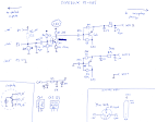
The schematics mostly adheres to the often copied "Schoeps" design, here's my attempt at the schematics.
I think I got the type of Q1 wrong. It's probably wired as an emitter follower (the voltage gain of the drawn common emitter amp of 22x would be unreasonably high) with Q1 being a KSA1015 PNP Epitaxial Silicon Transistor. Q2 and Q3 are likely KTA1268
EPITAXIAL PLANAR PNP TRANSISTOR.
The PCB is small enough to fit it inside one of the earcups of the HMC660. Just cut open the direct connection that go from the 6-conductor XLR & TRS cable (braided copper, yellow, green) to the 3 wires that make their way into the gooseneck (white, black, red).
Here's the PCB inside a piece of heat-shrink tubing, but in the end, I opted to just hot-glue the bare PCB into the cup. Also some foam (from inside the PS-418's small shipping box) was added to prevent the whole thing from rattling around.
Here you go. 39€ + 19,90€ for a only halfway crappy headset ;-).
 |
| From Chris’ Miscellanea |
The microphone part is glued, but after heating it gently to about ~40..50 °C with a hair-dryer or a heating gun used for heat-shrink-tubing, it can just be pulled apart by hand.
 |
| From Chris’ Miscellanea |
The proper way to adress the connection issue is to use a proper phantom-power adapter for electret microphones, luckily this taiwanese producer of cheap (and a little crappy) audio electronics also has something in store. The Superlux PS 418-S adapter!
Inside, this little marvel looks like this: Mostly through hole, one-sided PCB, waves-soldered.
 |
| From Chris’ Miscellanea |
The schematics mostly adheres to the often copied "Schoeps" design, here's my attempt at the schematics.
 |
| From Chris’ Miscellanea |
I think I got the type of Q1 wrong. It's probably wired as an emitter follower (the voltage gain of the drawn common emitter amp of 22x would be unreasonably high) with Q1 being a KSA1015 PNP Epitaxial Silicon Transistor. Q2 and Q3 are likely KTA1268
EPITAXIAL PLANAR PNP TRANSISTOR.
The PCB is small enough to fit it inside one of the earcups of the HMC660. Just cut open the direct connection that go from the 6-conductor XLR & TRS cable (braided copper, yellow, green) to the 3 wires that make their way into the gooseneck (white, black, red).
 |
| From Chris’ Miscellanea |
 |
| From Chris’ Miscellanea |
Here's the PCB inside a piece of heat-shrink tubing, but in the end, I opted to just hot-glue the bare PCB into the cup. Also some foam (from inside the PS-418's small shipping box) was added to prevent the whole thing from rattling around.
 |
| From Chris’ Miscellanea |
Here you go. 39€ + 19,90€ for a only halfway crappy headset ;-).
Wednesday, March 23, 2016
W&T 36201 Isolated USB to RS485 Interface: Fix "automatic" RS485 Transmit mode
Some time ago, I bought three used W&T 36201 isolated USB to RS485 interfaces. They have pretty good build quality and are intended to be mounted in control cabinets (on “DIN Rails”). You can see them in this photograph, it's the blue thing.
And while I'm pretty impressed by their build quality, I found out that even for (normally pretty expensive) industrial kit, they get the control of RS485 transmission wrong.
RS485, in short, is a pair of cables named A and B which carry a differential signal. This means that the signal in one wire should always be the inverse of the signal in the other wire: If voltage on A increases, the voltage on B should decrease. The state of the bus is “1” when the voltage on B is higher than the voltage on A, and the state of the bus is “0” when the voltage on B is lower than the voltage on A. A RS485 bus, when idle, is kept at the level corresponding to a “1” bit by the termination voltage, which pull B to a higher voltage than A, keeping an impedance of 100 Ohms on the differential pair A and B.
When data is exchanged over the bus, the first thing being transmitted is the stop bit, at “0” level, then the first byte, ... until transmission is completed. Naively, one would think that a driver only has to supply the “0” level and let go of the wires, making the termination resistors pull them to “1” again.
Unfortunately, these resistors aren't typically able to do this fast enough, especially for higher baud rates, and active drive of the bus therefore must be maintained throughout the complete transmission.
Thus, we need some control signal that tells the driver IC when to turn on its output drivers, and there are several methods for this.
Here's a (very slow) 9600 baud transmission via the unmodified interface in "automatic" mode. The driver is only activated (blue) during 0-bits.
The used USB to UART bridge fortunately has a TXEN pin (#16), which we jumper over to the line normally carrying the #DTR (inverted) signal that can be used to implement method (2). The chip is mounted on a separate small PCB which makes working on it pretty easy:
Unfortunately the polarity of TXEN is high-active, but as built the converter needs #DTR to go LOW to transmit. So we use a spare gate of the HC04 hex inverter conveniently located on the baseboard. One has to scratch open the very short trace between the pullup for the optocoupler and the via left to it.
After this modification, set the device to computer-controlled transmit control (normally DTR, now TXEN). As can be seen on the scope, now the transmitter IC drives the bus for the whole duration of a character.
 |
| From Chris’ Miscellanea |
And while I'm pretty impressed by their build quality, I found out that even for (normally pretty expensive) industrial kit, they get the control of RS485 transmission wrong.
RS485, in short, is a pair of cables named A and B which carry a differential signal. This means that the signal in one wire should always be the inverse of the signal in the other wire: If voltage on A increases, the voltage on B should decrease. The state of the bus is “1” when the voltage on B is higher than the voltage on A, and the state of the bus is “0” when the voltage on B is lower than the voltage on A. A RS485 bus, when idle, is kept at the level corresponding to a “1” bit by the termination voltage, which pull B to a higher voltage than A, keeping an impedance of 100 Ohms on the differential pair A and B.
When data is exchanged over the bus, the first thing being transmitted is the stop bit, at “0” level, then the first byte, ... until transmission is completed. Naively, one would think that a driver only has to supply the “0” level and let go of the wires, making the termination resistors pull them to “1” again.
Unfortunately, these resistors aren't typically able to do this fast enough, especially for higher baud rates, and active drive of the bus therefore must be maintained throughout the complete transmission.
Thus, we need some control signal that tells the driver IC when to turn on its output drivers, and there are several methods for this.
- some RS485 adapters cheat by only transmitting the “0” in full, and only output a very short “1” runt pulse to charge up the bus, leaving maintaining the idle voltage to the termination resistors,
- some RS485 adapters use a serial control line (RTS, DTR) as a control signal and
- many USB to RS485 adapters use a signal provided by the USB-UART for exactly this purpose.
Unfortunately the W&T 36201 interfaces only do 1 and 2, so I tried to modify them to provide for 3.
Here's a (very slow) 9600 baud transmission via the unmodified interface in "automatic" mode. The driver is only activated (blue) during 0-bits.
 |
| From Chris’ Miscellanea |
The used USB to UART bridge fortunately has a TXEN pin (#16), which we jumper over to the line normally carrying the #DTR (inverted) signal that can be used to implement method (2). The chip is mounted on a separate small PCB which makes working on it pretty easy:
 |
| From Chris’ Miscellanea |
 |
| From Chris’ Miscellanea |
Unfortunately the polarity of TXEN is high-active, but as built the converter needs #DTR to go LOW to transmit. So we use a spare gate of the HC04 hex inverter conveniently located on the baseboard. One has to scratch open the very short trace between the pullup for the optocoupler and the via left to it.
 |
| From Chris’ Miscellanea |
After this modification, set the device to computer-controlled transmit control (normally DTR, now TXEN). As can be seen on the scope, now the transmitter IC drives the bus for the whole duration of a character.
 |
| From Chris’ Miscellanea |
Sunday, February 28, 2016
ASUS RT N12E Bootup
Debugging a problem with a ASUS RT-N12E 300Mbps Wireless N Router, I soldered a pin header to J15 (next to the ethernet magnetics handling the yellow "LAN" ports).
Pinout is Vcc, GND, Tx, Rx. Vcc is the square pad, Rx and Tx as seen from the N12E soc. Port runs at 38400 bps.
Here's the bootup messages, just in case anyone is interested.
$ cu -l ttyUSB0 -s 38400
Connected.
========== SPI =============
SDRAM CLOCK:156MHZ
------------------------- Force into Single IO Mode ------------------------
|No chipID Sft chipSize blkSize secSize pageSize sdCk opCk chipName |
| 0 c22016h 0h 400000h 10000h 1000h 100h 86 39 MX25L3205D/E|
----------------------------------------------------------------------------
Set 8196C PHY Patch OK
---RealTek(RTL8196C)at 2013.12.09-17:34+0800 version v1.1f [16bit](390MHz)
####return_addr: 0x05010000, root_bin_offset: 0x050dd012
Jump to image start=0x80500000...
decompressing kernel:
Uncompressing Linux... done, booting the kernel.
done decompressing kernel.
start address: 0x80003600
RTL8192C/RTL8188C driver version 1.6 (2011-07-18)
Probing RTL8186 10/100 NIC-kenel stack size order[2]...
chip name: 8196C, chip revid: 4
NOT YET
eth0 added. vid=9 Member port 0x10...
eth1 added. vid=8 Member port 0x1...
eth2 added. vid=9 Member port 0x2...
eth3 added. vid=9 Member port 0x4...
eth4 added. vid=9 Member port 0x8...
[peth0] added, mapping to [eth1]...
init started: BusyBox v1.13.4 (2014-09-18 18:08:32 CST)
##flash.c free apmib ##
Init Start...
wan_disconnect: option all
##system/sysconf.c free apmib ##
##flash.c free apmib ##
===== Set parameter for BSMI test=====
Init bridge interface...
wait for bridge initialization...
syslog will use 64KB for log(7 rotate, 1 original, 8KB for each)
route: SIOCDELRT: No such process
route: SIOCADDRT: Invalid argument
Init Start...
Init Wlan application...
##flash.c free apmib ##
##flash.c free apmib ##
update wps state to -1
WiFi Simple Config v2.9-wps2.0 (2014.09.18-10:09+0000).
Init Wlan application...
##flash.c free apmib ##
##flash.c free apmib ##
update wps state to -1
WiFi Simple Config v2.9-wps2.0 (2014.09.18-10:09+0000).
Register to wlan0
iwcontrol RegisterPID to (wlan0)
Register to wlan0
##system/sysconf.c free apmib ##
iwcontrol RegisterPID to (wlan0)
Init Firewall Rules....
firewall clean prerouting
firewall add iptables rule
No wan ip currently!
System TZ ENV = GMT-8
##system/sysconf.c free apmib ##
start infosvr
WLAN0_WLAN_DISABLED=0 ##flash.c free apmib ##
sh: ##flash.c: unknown operand
# Start httpd!
Start wanduck!
# <-- :-="" a="" b="" here="" rootshell="" s="">
MemTotal: 11144 kB
MemFree: 5164 kB
Buffers: 224 kB
Cached: 1128 kB
SwapCached: 0 kB
Active: 1672 kB
Inactive: 716 kB
Active(anon): 1036 kB
Inactive(anon): 0 kB
Active(file): 636 kB
Inactive(file): 716 kB
SwapTotal: 0 kB
SwapFree: 0 kB
Dirty: 0 kB
Writeback: 0 kB
AnonPages: 1044 kB
Mapped: 716 kB
Slab: 3064 kB
SReclaimable: 176 kB
SUnreclaim: 2888 kB
PageTables: 164 kB
NFS_Unstable: 0 kB
Bounce: 0 kB
WritebackTmp: 0 kB
CommitLimit: 5572 kB
Committed_AS: 2220 kB
VmallocTotal: 1048404 kB
VmallocUsed: 264 kB
VmallocChunk: 1048136 kB
# cat /proc/cpuinfo
system type : RTL8196C
processor : 0
cpu model : 52481
BogoMIPS : 389.12
tlb_entries : 32
mips16 implemented : yes
# busybox
BusyBox v1.13.4 (2014-09-18 18:08:32 CST) multi-call binary
Copyright (C) 1998-2008 Erik Andersen, Rob Landley, Denys Vlasenko
and others. Licensed under GPLv2.
See source distribution for full notice.
Usage: busybox [function] [arguments]...
or: function [arguments]...
BusyBox is a multi-call binary that combines many common Unix
utilities into a single executable. Most people will create a
link to busybox for each function they wish to use and BusyBox
will act like whatever it was invoked as!
Currently defined functions:
arp, ash, bunzip2, bzcat, cat, cp, cut, date, echo, expr, false,
free, grep, gzip, halt, head, hostname, ifconfig, init, ip, kill,
killall, klogd, ln, ls, mkdir, mount, ping, poweroff, ps, reboot,
renice, rm, route, sh, sleep, sync, syslogd, tail, telnetd, top,
true, umount, vconfig, wc, zcip
Sunday, February 21, 2016
Linux/udev: Unbinding from one kernel driver, and rebinding to a different one. Automatically, using udev.
Quite a lot of USB devices claim to be a human interface device, the rationale being that you can access them on Windows without the need to supply your own "proper" driver.
Under Linux, one can easily unbind the usbhid driver from a particular usb device, but this gets tedious after a few dozen times. But there's a workaround using udev and a short script to rebind to a different kernel module.
First, create a udev rule, e.g. in /etc/udev/rules.d/99-rebind-driver.sh:
(all in one line)
Then use the following small script, stored as /usr/local/sbin/rebind_sysfs_driver.sh to do the actual work:
#!/bin/sh
if [ "$#" != 3 ] ; then
echo "Usage: $0 sysfs_path kernel_name new_driver_path" >&2
echo "" >&2
echo "To be used in udev rules:" >&2
echo " RUN+=\"$0 %p %k /bus/usb/drivers/mcp2210\"" >&2
echo "which rebinds a particular device to a new driver." >&2
exit 1
fi
set -e
logger -t "$0" "Rebind device $1($2) to driver $3."
cd "/sys$1"
echo "$2" >driver/unbind
sleep 1
Under Linux, one can easily unbind the usbhid driver from a particular usb device, but this gets tedious after a few dozen times. But there's a workaround using udev and a short script to rebind to a different kernel module.
First, create a udev rule, e.g. in /etc/udev/rules.d/99-rebind-driver.sh:
ACTION=="add", DRIVER=="usbhid", SUBSYSTEMS=="usb",

ATTRS{idVendor}=="04d8", ATTRS{idProduct}=="00de",

RUN+="/usr/local/sbin/rebind_sysfs_driver.sh %p %k /bus/usb/drivers/mcp2210"
(all in one line)
Then use the following small script, stored as /usr/local/sbin/rebind_sysfs_driver.sh to do the actual work:
#!/bin/sh
if [ "$#" != 3 ] ; then
echo "Usage: $0 sysfs_path kernel_name new_driver_path" >&2
echo "" >&2
echo "To be used in udev rules:" >&2
echo " RUN+=\"$0 %p %k /bus/usb/drivers/mcp2210\"" >&2
echo "which rebinds a particular device to a new driver." >&2
exit 1
fi
set -e
logger -t "$0" "Rebind device $1($2) to driver $3."
cd "/sys$1"
echo "$2" >driver/unbind
sleep 1
echo "$2" >"/sys$3/bind"
Subscribe to:
Posts (Atom)